
A single loop or ring main pipe network is shown below.
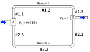
It is a common, reliable and efficient pipe network that engineers would normally adopt in his/her design such as hydrant ring main application, irrigation system, etc.

However, to determine the pressure drop or friction loss in the loop pipe network is not as easy and simple as the one in series pipe network. More often, engineers (count me in) use rule of thumb to estimate the pressure drop as the actual calculation itself (without a computer program) is too tedious and time consuming. The most common and popular method used to calculate the friction loss in a loop pipe network is the Hardy Cross Method (Wiki’s here).
As an engineer, I always think of a simple and effective way to solve a task; explore better methods to do things. In 2015, I spent a lot of time in engineering a program called ePF (easy Pipe Friction) Loop – a simple yet effective solution provider for multi-purpose applications. No pipe network modelling is required. Simple application does not require a complex software to perform the solution. If you need a complex software for your application, you may try EPANET.
Example – Simple analysis of a single loop ring main
In the loop piping system as shown in the diagram above, the pressure at Node A is 965 kPa, and the total flow rate of water is 0.70 m3/s. Pipe lengths and diameters are as follows:
for branch 1: total pipe length = 550m, diameter = 0.36m
for branch 2: total pipe length = 850m, diameter = 0.50m
The pipe material is Ductile Iron cement-lined pipe. Neglect minor losses, determine the pressure at Node B.
ePF answers:
The snapshot below shows the inputs and results. Note that as only the total pipe length is given for Branch 1, pipe #1.1 and #1.2 are modeled as zero length. Similar for Branch 2.
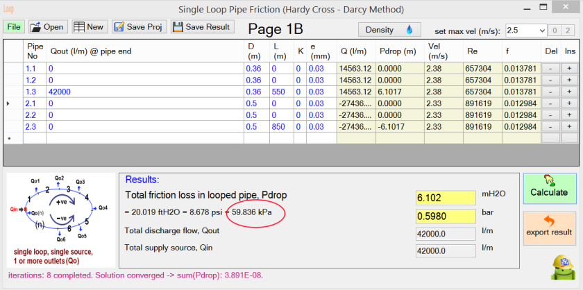
Given PA = 965 kPa, so PB = 965 – 59.836 = 905.164 kPa
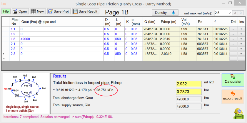
Alternative Design scheme: (reduce pressure drop)
If the pipe diameter in Branch 1 is increased to 0.50m (same diameter as Branch 2), the pressure drop in the looped pipe will reduce by (59.836 – 28.751) = 31.085 kPa (approx. 52%).
Additional Analysis: (motor kW estimation)
Motor kW calculations are done with aPipeSizer (Android version) program.
Assume pump efficiency of 70% and motor efficiency of 85%.
To move the flow with 59.836 kPa head, motor kW required is approx. 70.4 kW.
To move the flow with 28.751 kPa head, motor kW required is approx. 33.8 kW.
Therefore, the motor kW is reduced by 36.6 kW (approx. 52%) in the Alternative Design scheme.